Asecure and sufficient
electricity supply is crucial
for industry driven economic
growth. To exemplify with a fast
developing nation, India has plans
to increase its installed capacity by
50 per cent between 2007 and 2012.
During the same period, the interregional
transmission capacity
between the Indian regions is likely
to be doubled.
Such a rapid development of power systems requires good
planning and practices of providing effective Reactive
power compensation devices like capacitors.
Capacitor is one of the most efficient and very high
power density devices. However, being a low impedance
member in an electrical system, all polluting elements like
harmonics tend to flow towards it and makes its
application more complicated.
This paper gives major application of capacitors, benefits,
associated problems and possible solutions.
APPLICATION
One of the most important benefits of providing
capacitors is to reduce losses of the power system. T&D
losses in the Indian context, even at a conservative
estimate, are around 40 per cent. This includes
commercial and technical losses. Some of the major factors
to the high technical losses are uses of lower conductor
sizes, low voltages; poor power factors that are lack of
reactive power in the system. In India major portion of
losses is accounted for in the low voltage sections. Low
voltages and poor power factors of induction motors
driving agriculture pumps compound this problem. The
reflection of the problem is even felt up to high voltage
side. For example a low voltage of 320kV was reported on
400kV line indicating severe shortage of reactive power.
Because of acute shortage of MVAR, the substantial
portion of generation capacity is getting wasted.
Table 1: Cost Comparison |
Equipment of 11kV capacitor |
Cost in multiple of single-step cost |
|
(`100/kVAr) |
|
Capacitors |
Capacitors |
Capacitors |
|
in 1-step |
in 2-step |
in 3-step |
| Total 2000kVAr 11kV capacitors |
1.00 |
1.10 |
1.20 |
| 6% Series reactors |
1.12 |
1.80 |
2.22 |
| RVT |
0.15 |
0.30 |
0.45 |
| Outdoor breaker |
1.50 |
3.00 |
4.50 |
| Isolator |
0.20 |
0.40 |
0.60 |
| Structures |
0.50 |
1.00 |
1.50 |
| Control panel |
0.60 |
0.90 |
1.20 |
| Interconnection |
0.05 |
0.10 |
0.15 |
| Total cost of supply |
5.12 |
8.60 |
11.82 |
| Cost in terms of 1-step |
1.00 |
1.68 |
2.31 |
The ideal way of attacking the problem is to provide
KVAR at the point where it is required that is at motor
terminal of agriculture pumps. State utilities with finances
from Rural Electrification Corporation (REC) is very well
aware of the problem and has done number of experiments
like making installation of capacitor compulsory for
providing connection, free distribution of capacitors,
providing capacitors on LT transformer feeding supply to
distribution net work including agriculture pumps, automatically switched capacitors etc. But so for success
rate is not satisfactory. Reasons can be attributed to: no
incentives to farmers providing capacitors, poor quality
of capacitors, malpractices etc.
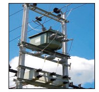
The next convenient point is on 11kV side. This is
midpoint of EHV lines and consumers to improve
voltages and reducing losses. Pole mounted capacitors
with auto switches were provided in large numbers.
Similarly substation capacitors both at 11kV and 33kV
were provided but this also failed. First apparent reason
was quality of capacitors and second was over
compensation during lean load conditions. Manual
capacitors used to be switched off during nighttime and
they continue to remain off during peak load hours.
Present scenario remains injecting flexible power that is
automatic switched Capacitor system (APFCR) either
directly on 11kV side or on 44VAC side at 11kV
substation by providing one 11kV/440VAC transformer
the new trend is providing automatically stage switched
capacitors at 11kV side.
CAPACITOR WITH AUTOMATIC POWER
FACTOR CONTROLLERS
Automatic PF correction panel are very common in use
in 415/440V system. These panels ensure correction of
the PF to desired level automatically which saves the
botheration of maintenance engineer to constantly
monitor the PF. It is the normal practice to provide HT
capacitors as fixed type to achieve major correction in PF
and then fine-tune the PF with LT APFC panels.
Nowadays customers are also going in for automatic PF
correction in high voltage like 3.3kV, 6.6kV and even
11kV. Due to the higher cost of breakers, contactors and
repetition of other equipments like reactors, RVTs,
isolators etc, the cost of providing automatic analysis in
terms of capacitor cost for 1, 2 & 3 steps automatic
correction is high.
It can be seen from Table 1 that for 2-step cost is more
than 1.5 times the cost of single step correction. Three
steps scheme can be more than two times the cost. If you
add erection and civil work then the cost of multiple
steps will further escalate. One should therefore make a
prudent choice before going in for multi step PF
correction scheme in high voltage capacitors. It is to be
remembered that the purpose of providing capacitors is
to save on electricity cost. If the cost of capacitor system
is very high the pay back becomes very long.
Considering all above, the best option in the present
scenario remains injecting flexible power that is automatic
switched capacitor system (APFCR) either directly on 11kV
side or on 44VAC side at 11kV substation by providing one
11kV/440VAC transformer.
Table 2: Voltage distortion limits |
| Bust voltage at PCC |
Individual
Voltage
Distortion
(%) |
Total
Voltage
Distortion
THD
(%) |
| 69kV and below |
3.0 |
5.0 |
| 69.001kV up to 16.1kV |
1.5 |
2.5 |
| 161kV and above |
1.0 |
1.5 |
HT Capacitor bank at 66kV,132kV and 220kV has also
been installed. The loads average out here and fluctuation s
between maximum and minimum are also not very high.
This takes care of minimum base load. This place has been
found satisfactory but major benefits are felt at Generators
and transmitters, and gives marginal improvement in the
overall system. There are other advantages of capacitors
some of which are:
- Improves voltage level of the system where they are
connected
- Reduction in load current reduces resistive losses, which
in turn reduces unit consumption.
- Releases capacity of transformer, which can then take
more loads
- Helps in reducing unnecessary tripping of motors due to
voltage dips
- Capacitors, with tuned reactors, filter out unwanted
harmonics and reduce THD levels to within limits of
IEEE-519.
CAPACITORS AS HARMONIC FILTERS
Increasing use of nonlinearly behaving power electronic
converters in industries and buildings has resulted in
generation of harmonic voltages and currents in
considerable levels. These harmonics often create problems
for the stable and economic operation of power systems.
Efforts are being made to reduce the level of harmonics
through the introduction of guidelines, recommended
practices and standards. A commonly adopted solution for
this problem is to install harmonic filters at suitable
location. Harmonic filter consists of properly designed
Capacitor- Reactor combination.
This serves the dual purpose of harmonic filter and
improvement of power factor. Software has been developed
to check the effect of various Filters, their effect on Total
Harmonic distortion levels. Based on optimum harmonic
filter systems are designed. In India large number of such
effective Filters are in operation at 440VAC, 11kV and 33kV
sides. IEEE-519 has specified limits of THD (Total
Harmonic Distortion), which are given in Table 2.
Capacitors offer lower impedance to higher harmonics.
Hence harmonics flow to capacitors causing overloading
and possible premature failure. There is also a risk of
resonance with any of the harmonic present in the system.
In such a case it can damage not only capacitor but also
other equipment in the line. Even if there is no resonance
there is magnification of harmonic currents causing higher
THD, which may exceed limits specified in IEEE-519.
It is very important to provide properly designed
harmonic filter after carrying out and analysis of proper
harmonic with different load conditions, eliminating the
possibility of resonance, checking transformer fault level,
impedances etc.
SIZING OF CAPACITOR BANK AND SERIES
REACTOR
When capacitor bank voltage is increased its out put
increases in square proportion. For example1 MVAr
capacitor if required at 11kV and the rated voltage is chosen
as 12.1kV, then the corrected rating at 12.1kV will be:
Rating of Capacitor in MVAr
= 1* (12.1*12.1/11*11)
= 1.21
When capacitor bank is provided with series reactor, say 6
per cent, the rating of capacitor needs to be corrected for
loss in series reactor? For the same requirement of 1 MVAr
at 11 KV, the rated voltage is chosen as:
Rated Voltage =11*1.1/(1- 0.06) kV
= 12.87 kV
Capacitor impedance at 11kV bus,
Xc = 11*11 / 1
= 121 ohms
Corrected capacitor impedance
Xc' = Xc/(1 - 0.06) ohm
= 121/0.94 ohms
= 128.72 ohms
Hence
Cap. Output = KV*KV / Xc'
= 12.87*12.87/128.72
= 1.28 MVAr
S R imp. = 0.06* Xc'
= 7.73 ohms
Hence 1.28 MVAr, 12.87kV capacitor bank with 6 per cent
series reactor will give 1 MVAr at 11 KV bus.
(P.K. Bhandari is Senior Vice President—Capacitor,
Universal Cables Ltd, Satna, Madhya Pradesh)
Untitled Document
Table 3: Maximum harmonic current distortion in % of IL |
(Current distortion limits for general distribution systems: 120V to 69,000V) |
Individual harmonic order (odd harmonics) |
| Isc/IL |
h <11 |
11h<17 |
17h<23 |
23 h 35 |
35 h |
TDD |
| <20* |
4.0 |
2.0 |
1.5 |
0.6 |
0.3 |
5.0 |
| 20<50 |
7.0 |
3.5 |
2.5 |
1.0 |
0.5 |
8.0 |
| 50<100 |
10.0 |
4.5 |
4.0 |
1.5 |
0.7 |
12.0 |
| 100<1000 |
12.0 |
5.5 |
5.0 |
2.0 |
1.0 |
15.0 |
| >1000 |
15.0 |
7.0 |
6.0 |
2.5 |
1.4 |
20.0 |
| Note: |
| Even harmonics are limited to 25 per cent of the odd harmonic limits above |
| Current distortion that results in a direct current offset (e.g. half wave converters not
allowed) |
| *All power generation equipmetn is limited to these values of current distortion,
regardless of actual Isc/IL |
| Isc=Maximum short circuit current at point-of-common-pooling |
| IL=Maximum demnd load current (fundamental frequency) at point of common
coupling |
| H=harmonic number |