
In the recent years, there is very often
this question, as to why the powerfactor
which is shown by a power
factor control relay different from the
power-factor which is shown by the
utility meter.
For this effect, there are different
reasons possible, e.g. measuring on
different places. Very often, these
differences in power-factor are
differences between power-factor ? or
PF and displacement power-factor cosf
or DPF.
Very often, there are compared two
different measuring values and both of
them are making sense.
ACTIVE POWER, REACTIVE
POWER, APPARENT POWER
Consumer load is converting depending
on the efficiency of the electrical energy
to work. This electrical load is shown in
a circuit diagram as a resistor. In
practical use, there is parallel to this
resistive load or active load some other
load, which is called reactive load.
Reactive load is used to build up
electric and magnetic fields. In a circuit
diagrams these loads are shown as
inductance and capacitance.
Inductances are causing a lagging of the
current, because current flow is only
possible after the voltage has built up
the magnetic field. Capacitances are
causing a leading current,
because the current flow has
to charge the capacitance.
These characteristics are
causing a displacement
between voltage and
current, when inductances
or capacitances are in an
electric circuit.
Resistive, capacitive and
inductive load are linear
loads. In a coordinate system
with voltage and current axis, you can
see the linear load as a line. The current
depends from voltage with a fix factor.
Parallel to linear loads, there are also
non-linear loads, e.g. rectifiers,
computers, UPS-systems, motordrives
or transformers which are used
in saturation. In a coordinate system
with voltage and current axis, you can
see non-linear loads as curves with
breaks and jumps. The relation
between voltage and current depends
on their values.
When a non-linear load is connected
to an AC-voltage source with pure sinewave,
then the current which is caused
by this load has differing wave form.
When this current wave-form is
analysed by Fourier-analysis, then you
get a summation of sinewaves with
multiple frequencies of the
fundamental wave, different phaseshifts
and different amplitude. These
wave forms are called harmonics.
For the calculation of the power, these
wave forms of all the voltages and
current waves must be multiplied. Real
power is only created by the parts of the
voltages and currents with the same
frequency. The value of the real power
depends on the amplitude and the
phase-shift of the two waves. In
systems with (almost) sine-wave
voltage, like it is in the real grid, only the
fundamental wave of the current is
important for calculation of real power.
The reactive voltage, which is caused
by the phase-shift between
voltage and fundamental
wave of the current, is
called displacement
reactive power. The
reactive power, which is
cause by the multiplication
between the current
harmonics and the voltage,
is called deformation
reactive power.
The apparent power is
the product of the RMS values of
current and voltage. Apparent
power is an important value for the
rating of electric power distribution.
Apparent power an also be
calculated by this formula:
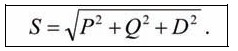
S= apparent power (kVA)
P= active power (kW)
Q= displacement reactive power (kvar)
D= deformation reactive power (kvar)
COMPARISON POWER
FACTOR ? (PF) -
DISPLACEMENT POWER
FACTOR COSf (DPF)
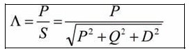
The power factor shows which part of
the apparent power, which is loading
the distribution, is the active or real
power. This factor is called Power Factor
with the sign ? or PF.
The formula for calculating the Power
Factor is:
The mean value for Power Factor can
be calculated by using this formula:
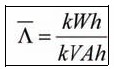
This calculation is used in utility
meters for calculating the mean value of
Power Factor in a period of time. Because
reactive power compensation with capacitors cannot compensate deformation reactive
power and because deformation reactive power was not so
important in the past, the cosf, which is calculated from
the phase-shift of the fundamental waves of current and
voltage, is used instead of the Power Factor.
This value can be calculated from the power with the
following formula:
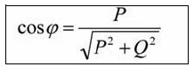
The deformation reactive power is not used in this
calculation.
REACTIVE POWER COMPENSATION
Reactive power compensation is used to use the capacity
of electric distribution systems in the optimal way. This
saves energy and it saves investment costs for the grid. A
common used way for reactive power compensation is
the compensation of displacement reactive power by
using capacitors.
Very often, these capacitors are
controlled by a reactive power
regulator. To get a correct
function of this regulator, then it
is necessary that the controlled
variable is the displacement
reactive power, because
switching capacitors has only a
direct influence to this. The target for compensation has
to be the cosf and not the Power Factor ?.
If a reactive power regulator is compensating to Power
Factor ?, then you will get problems like
overcompensation of the displacement reactive power or
hunting.
A simple example for this is:
P = 100kW; Q = 50kvar; D = 50kvar; cosf (DPF) = 0.89
? (PF) = 0.82
A regulator, which is using target cosf (DPF) = 0.89, will
switch 50kvar, will reach cosf (DPF) = 1.00 and ? (PF) =
0.89
A regulator, which is using ? (PF) = 0.82, will switch
69kvar, will reach cosf (DPF) = 0.98 and ? (PF) = 0.88.
This example is showing, that by using target ? (PF)
more installed capacitors are necessary and a worse
result of compensation is achieved compared by using
cosf (DPF) as target.
This example shows that it's wise to use BELUK
reactive power regulators (power factor control relays),
which are using displacement reactive power as control
variable. The showing of cosf (DPF) instead of ? (PF) is
also possible on these devices.
It's intelligible, when utility companies want to
reach Power Factor ? (PF) = 1.000. To reduce the
deformation reactive power, which is responsible for
the difference between ? (PF) and cosf (DPF),
harmonic filters are needed.
[Michael Reith is General Manager, BELUK GmbH,
Germany]