 —Bratin Roy, Assistant Vice President & Head — Energy & Environment Services, TUV SUD South Asia.
 In this exclusive interaction, we have
Bratin Roy sharing keen insights into the phenomenon of power factor correction. Right from explaining the concept of power factor and why an unhealthy power factor merits correction, Roy asserts that maintaining a healthy power factor can bring about tremendous efficiency in an electrical circuit. With India’s power consumption expected to grow at faster rates, power factor correction is destined to play a vital role, notes Roy. An interview by
Venugopal Pillai.
Please explain in simple terms what power factor means, and why it needs to be corrected or improved.
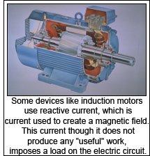
All machines such as motors, transformers etc. depend on magnetism. While working, it produces magnetic forces and the electrical current needed for this purpose is not fully utilised. This current is called the reactive current in contrast to the active current which performs work and is fully utilized for work. Therefore, the necessary current (active component) is generally less than current flowing in AC circuit.
Geometrical calculation of these two powers is indicated by a factor called as power factor. Power factor is the ratio of real power to apparent power. When both current and voltage are sinusoidal and in-phase, the power factor is one. If they are sinusoidal but not in-phase, then the power factor is the cosine of the phase angle. Purely sinusoidal current and voltage waveforms occur when the load comprises resistive, capacitive, and inductive elements that are all linear.
Although the reactive current is not utilised, it imposes a load on the electrical distribution system and supply authorities demand payment for this load according to specific tariffs. In addition to this, it decreases plant energy efficiency due to some of the factors such as overloading of cables, change in torque of motors etc. As the general current is more than the required, utilities must design their systems with oversized equipment to accommodate reactive current. In order to pass along the expense of the larger equipment required and the system losses from the flow of the reactive current, many utilities will charge their customers a penalty for low power factor. There are a variety of means in which this penalty is calculated by the utility.
Personnel at manufacturing and commercial buildings must monitor this attribute of their electrical power if they’re going to keep costs under control and not continually waste money on a monthly basis. Every added fluorescent light, transformer or motor has the potential to change the power factor, and electric company may be reaping the benefits in the form of extra charges and penalties.
 Is there any estimate of how much energy saving is technically possible through power factor correction, going by the country’s current power consumption pattern?
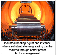
Every country spends huge amounts of money and natural resources in the production and distribution of electric power. Electric power is required by us for almost all stationary power requirements. Industrial loads such as heating, cooling, lighting, motion etc. are the major power consumers and have major potential for energy saving from power factor correction. Energy saving due to power factor correction is substantial in all the areas such as generation (at plant and substation), transmission and distribution sector (commercial and HT consumers), residential sector etc. It is difficult to arrive at any figure for energy saving through power factor correction for the country. However, our experience indicate that, with proper implementation of corrective measures, 10-40 per cent of total plant/system losses can be minimized by correcting power factor from 0.8 to 1.0
Are there some fixed standards that countries follow in determining the ideal power factor ratio? What is the scenario in India?
Power factors below 1.0 require a utility to generate more than the minimum volt-amperes necessary to supply the real power (watts). This increases generation and transmission costs. (since they are proportional to the square of the current). Alternatively, all components of the system such as generators, conductors, transformers, and switchgear would be increased in size (and cost) to carry the extra current. Utilities in India charge additional costs to customers who have a power factor below some limit, which is typically 0.9 to 0.95.
International standards IEC 555-2 “Harmonic injection into the AC Mains” and IEC 555-3 “Disturbances in supply systems caused by household appliances and similar electrical equipment - Part 3: Voltage fluctuations” were published. Like those standards, the current standards come out of Europe, but they’re nearly universal. There are related government regulations for power-line harmonics in Japan, Australia, and China. In the European Union, standard IEC/EN61000-3-2, “Electromagnetic compatibility (EMC) - Part 3-2 - Limits - Limits for harmonic current emissions (equipment input current = 16 A per phase),” sets current limits up to the 39th harmonic for equipment with maximum power-supply specs from 75 to 600W. Its “Class D” requirements (the strictest) apply to personal computers, computer monitors, and TV receivers. (Classes A, B, and C cover appliances, power tools, and lighting.) IEC61000-3-2, being a European-oriented standard, is based on 230V single-phase and 230/400V three-phase power at the wall-plug. In consequence, the current limits have to be adjusted for 120/240V mains voltages in North America. Therefore, there are voluntary standards for North America.
We understand that power utilities penalize industrial electricity consumers who fail to maintain a healthy power factor ratio. What is your view?
All electrical drawings of new HT consumers should be approved by CEIG (Chief Electrical Inspector to Government) against the available proper capacitors and automatic power factor controller in their electrical systems for maintaining zero level KVAR losses (Maintaining Unity Power Factor). All existing HT consumers, if not maintaining Unity Power Factor, should implement adequate capacitors with automatic power factor controller in their electrical systems for maintaining ZERO level KVAR losses (Maintaining Unity Power Factor) within few months of period time. Further, consumption by all HT consumers should be billed through KVAH units and not by KWH units.
 Do you feel that there is scope for energy efficiency by correction power factor even at the residential level? What could be possible causes for poor power factor in the domestic sector?
Appliances used for space conditioning such as air conditioner, lighting such as electronic ballast, cooking such as microwave and heating such as geysers always have low power factor than 1.0. Lighting load in India is more than 20 per cent of the installed generation capacity, so with deliberate strategies and rigorous implementations for reducing harmonics and improving power factor, this lighting load can be reduced drastically. There is huge potential for energy saving in India in this sector. Lot of the utilities started implementing demand side management initiative in lighting sector in India, which will result into substantial energy saving and improving power quality as well.
As India’s power requirement grows, it would be necessary to ensure that there is efficiency even in terms of consumption. Do you therefore think that power factor correction solutions will have a greater role to play in the coming years?
Yes. Power factor correction solutions will have a greater role to play in the coming years and it is also important to choose appropriate solutions depending upon the facility. In general, PFC (power factor correction) is either passive or active. Government and industry regulations specify only the power factor and the THD, leaving the decision about whether to use a passive or an active circuit to the design engineer.
Passive PFC is a simple, relatively inexpensive approach, but has its drawbacks. Chief among them is that it is difficult, although not impossible, to get a power factor of more than 0.7, and the trend in global regulations is toward power factors of 0.9 and higher. Another difficulty with passive PFC is that the capacitors go directly on the AC line, necessitating capacitor ratings of 400V or higher. This requirement makes the use of electrolytic capacitors the most common approach. Electrolytic capacitors’ lifetime drops with higher temperatures, so you must derate the capacitor if your system will need to work in a hot environment. To derate it, you must either choose a higher temperature, more-expensive capacitor or allow for a shorter capacitor lifetime. Another drawback with passive PFC is that its voltage output is unregulated as it feeds into the DC/DC-conversion stage. For these reasons, the trend is toward active PFC, usually in the form of a boost-converter circuit between the bridge rectifier and the storage capacitor.
The most common configurations for an AC/DC power supply with PFC are two-stage and single-stage designs. In a two-stage design, the ac line feeds into an AC/DC converter, usually comprising a bridge rectifier feeding into a capacitor whose output is usually full of second-harmonic ripple. A DC/DC converter follows the AC/DC converter to provide electrical isolation and voltage regulation. This approach keeps the two stages separate, is easy to troubleshoot, and is simple. However, the double conversion is less efficient, and costs are higher because of the need for two stages. As PFC becomes more prevalent, single stage PFC is becoming more common.
What services does TUV-SUD offer in the field of power factor correction? How do you view growth in the Indian business in the medium term?
Our specialists carry out thorough engineering analysis for power factor correction at a facility with harmonics. As power factor correction capacitors are installed, it’s critical to take into consideration any harmonic distortion that may be generated from a variety of sources inside or outside of facility. The presence of harmonics presents a challenge to using only capacitors for power factor correction. In some cases, there are unwanted interactions between the capacitors and the harmonic voltages and currents. Our engineers help to determine exactly what type of PFC solution you need and coordinate the installation so as to disrupt the facility as little as possible.