
As the deployment of
Fiber to the Home
(FTTH) technologies
in the access network
accelerates, Passive Optical
Network (PON) has become
area of focus among global
broadband operators and
been regarded as one of the
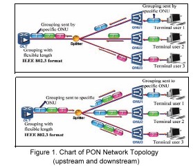
best method. It consists of
Optical Line Terminal
(OLT), Optical Distribution
Network (ODN) and Optical Network Unit (ONU). Its
relatively simple and transparent network structure which
makes it to be commonly used broadband access technique.
The ODN shares more than half of the total initial
investment of FTTH deployment. Its quality of planning
and construction will have tremendous impacts on the
future costs of mass operation and maintenance. ODN is
currently the focus of operators from all countries,
especially in Customer Premises Network (CPN), i.e. in the
last 100 m of fiber access.
3M is the first advocator and implementer of FTTH
solution worldwide. 3M has leading edge products and rich
experience in fiber connection technology.
ODN structure involves connectivity to various types of
buildings like Residential, Commercial buildings or
Industrial park that requires differential treatment in
design and deployment.
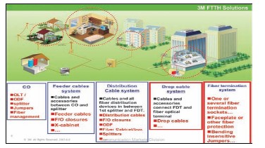
No matter what kind of building type, FTTH network based
on PON can be divided into five parts: (1) Subsystem of optical
fiber terminals (2) Subsystem of lead-in optical cable (3)
Subsystem of optical distribution cable (4) Subsystem of trunk
optical cable (feed line) and (5) Subsystem of central
machinery room.
These subsystems address the requirement from access
room where OLT is placed to the user where ONU is located.
CORE CONCEPT OF ODN DESIGN
3M has found out through its knowledge of domestic fixed
operators network and deploying capability that in the
construction of basic network, the operators are mostly
concerned about the subsystem of optical fiber terminals,
subsystem of lead-in optical cable and subsystem of optical
distribution cable in ODN structure.
Considering the concerns of domestic operators, factors
like basic network structure, and its core technology and
products, 3M put forward the following 4 core concepts for
ODN deployment:
Concept of fiber termination: Optical fibers are required
to be terminated and protected in the socket no matter
where they are (just like the termination of telephone line,
copper data line and coaxial cable for cable TV).
On-site termination of optical fiber: In CPN and user's
rooms, the fiber plugs and sockets shall be made on-site
instead of the traditional pigtail/patch cord of fixed length
made in factory.
Application of fiber mechanical connection technology:
In CPN and user's rooms, the fibers shall be connected by
mechanical connection instead of fusion splicing so as to avoid high investment & maintenance costs, and enable
quick connections.
Adopting special FTTH optical cable: Special optical cable
for FTTH should be adopted to ensure the flexibility, security,
and reliability of wiring in buildings and indoors.
The purpose of the four concepts is to make the
design, implementation, maintenance, and service of
fiber lines as convenient and reliable as those of copper
cable system.
SUBSYSTEM OF OPTICAL
FIBER TERMINALS
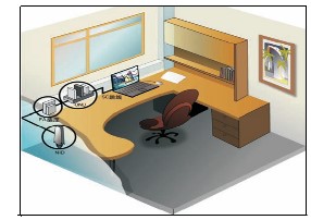
The fiber terminal subsystem include one or several fiber
termination sockets, and fiber patch cord connected to the
terminal device (ONU) with super flexural and pressure
resistance to avoid damage to cables and to human bodies.
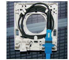
On-site SC connector is fixed without processes of
glue injection, heating, or polishing. It is advisable to
retain at least 100cm long optical cable in the socket for
future maintenance.
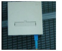
3M's has specially designed fiber terminal sockets 86-
type and 120-type which are widely deployed all around
the world for such applications.
The Glass/Glass Polymer (GGP) super strong fiber
patchcord technology of 3M Company has outstanding
resistance against external mechanical force. There is no
bending loss induced when the diameter is decreased from
15mm to 6mm.
For commercial buildings, there might be uncertainty in
business requirements and high possibility of
modification. It is suggested to follow TSB-75
International Standard. The socket is recommended to be
installed 30cm above the ground & should be at least one
fiber terminal socket in every 10 to 100 square meters or as
per actual requirement.
For the residential apartments, the optical distribution
cable should be installed in the distribution box on the
building corridor (the corridor distribution box is defined in
the distribution subsystem) or other distribution facilities.
Flexible connection or fixed connection can be used in
corridor distribution box to connect the optical distribution
cable with the lead-in cable. Mechanical splice is
recommended for fixed connection.
The mechanical connection does not need welder. It
only uses simple tools and realize the permanent single
core or multiple-core connection by mechanical
connection technology.
SUBSYSTEM OF LEAD-IN OPTICAL CABLE
The subsystem of lead-in optical cable is composed of cables
and accessories connecting the user's fiber terminal socket and
the building's distribution equipment.
The lead-in optical cable will be connected to the optical
fiber terminal socket in the way of on-site termination. The
lead-in cable would have of small bending radius (15mm) to
route around the corners and it is recommended to be made of
ITU G.657A optical fibers.
Optical distribution cable can also be directly lead-in into
the room in the insertion for some villas or independent users.
In this circumstance, there is no distinction between optical
distribution cable and lead-in optical cable.
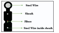
The lead in cables has special construction like rubber
covered optical self-supporting cable with steel core or without steel core. In terms of number of cores, it can be
divided into single core, 2 cores, and 4 cores, 8 cores cables, of
which the 2 cores, 4 cores, or 8 cores are distinguished by cover
of different colors. As for the performance, its pressure
resistance and tensile strength are all better than the loose
sheath and tight sheath optical cables that are widely used
now a day in the field.
SUBSYSTEM OF OPTICAL
DISTRIBUTION CABLE
The distribution subsystem is composed of the distribution
box at the corridor (for villa and other independent user, it
may refer to other optical fiber distribution equipment),
optical cables that link the building distribution box and
optical distribution points, optical splitter and cable
connecting accessories.
The optical distribution point is where the optical splitter
locates. A splitter is fiber optic network component that
combine multiple optical channels or divide a single channel
into two or more channels. A single optical channel is split into
32 or more individual channels, each carrying the same
information. In PON, single or two level splitting can be
adopted. Along the downstream direction, the section from
the starting point of the first splitter to the starting point of the
second splitter is the first level distribution subsystem. Section
from the second splitter to the building distribution box is the
second level distribution subsystem.
Designing of splitters takes into consideration of balancing
all the factors such as the initial investment and maintenance
costs, and be based on the principles of easy to implement and
test collectively, saving optical cable resources, saving the
work amount of opening and canceling a user, easy for
maintenance insertion and failure detection, etc. It is
recommended that the splitter shall be as close to the user as
possible. The optical splitter shall be linked to the optical
distribution cable by flexible connection method.
The position and volume of optical distribution facilities
such as distribution box at the corridor should be planned
rationally taking into consideration of current and future
connections & according to the building structure. The optical
cable shall be connected flexibly or fixedly inside.
SUBSYSTEM OF FEEDER OPTICAL CABLE
The feeder optical cable subsystem includes the optical
splitter, optical cables of central machinery room, and other
accessories. These accessories include the cable terminal box
that links and distributes the feeder optical box, the optical
cable cross connection cabinet, distribution box, ODF, etc.
 SUBSYSTEM OF CENTRAL
MACHINERY ROOM
SUBSYSTEM OF CENTRAL
MACHINERY ROOM
The central machinery room is configured according to the
access network room. The subsystem of central machinery
room mainly includes OLT and ODF as well as the relevant
devices and optical fiber management system. If optical
splitter is installed on the optical fiber distribution rack, the
connection of splitter outlet and feeder shall be flexible for easy
test and management.
To conclude designing of optical distribution network
(ODN) plays an important role affecting the cost of delivery
and flexibility in providing the connectivity. Careful
consideration has to be given in choosing the products which
are scalable, ease of installation and cost effective.
About the author: Navin Jacob Mathews is General Manager-
Communications Market Division, 3M.